Iranian Classification Society Rules

< Previous | Contents | Next >
PART A MANDATORY CRITERIA
CHAPTER 1 GENERAL
1.1 Application
This Guidance applies to ships engaged on international voyages, and ships not engaged on interna- tional voyages are to be compliance with the relevant local regulations of the flag states in which ships are flying.
1.1.1 The criteria stated under Ch 2 of this Part present a set of minimum requirements that shall
apply to cargo* and passenger ships of 24 ![]() in length and over.
in length and over.
* For containerships of 100 ![]() in length and over, provisions of 2.3 of Pt B may be applied as an alternative to the application of 2.2 of this Part. Offshore supply vessels and special pur-
in length and over, provisions of 2.3 of Pt B may be applied as an alternative to the application of 2.2 of this Part. Offshore supply vessels and special pur-
pose ships are not required to comply with provisions of 2.3 of Pt A. For offshore supply
vessels, provisions of 2.4 of Pt B may be applied as an alternative to the application of 2.2
of this part. For special purpose ships, provisions of 2.5 of Pt B may be applied
native to the application of 2.2 of this Part.
as an alter-
1.1.2 The criteria stated under Ch 3 are special criteria for certain types of ships. For the purpose
of Pt A the definitions given in the INTRODUCTION apply.
Guidance Relating to the Rules for the Classification of Steel Ships 2015 79
Pt 1 Classification and Surveys
Annex 1-2 Guidance for Intact Stability Pt 1, Annex 1-2
![]()
CHAPTER 2 GENERAL CRITERIA
2.1 General
2.1.1 All criteria shall be applied for all conditions of loading as set out in Pt B, 3.3 and 3.4.
2.1.2 Free surface effects(Pt B, 3.1) shall be accounted for in all conditions of loading as set out in Pt B, 3.3 and 3.4.
2.1.3 Where anti-rolling devices are installed in a ship, the ship shall comply with the relevant pro- visions of this Guidance when the devices are in operation and when the failure of power sup-
ply or the failure of the device(s) has occurred.
2.1.4 A number of influences such as icing of topsides, water trapped on deck, etc., adversely af- fect stability and the Administration is advised to take these into account, so far as is deemed necessary.
2.1.5 Provisions shall be made for a safe margin of stability at all stages of the voyage, regard be- ing given to additions of weight, such as those due to absorption of water and icing and to losses of weight such as those due to consumption of fuel and stores.
2.1.6 Each ship shall be provided with a stability booklet, approved by the Administration, which contains sufficient information(see Pt B, 3.6) to enable the master to operate the ship in com- pliance with the applicable requirements contained in the Guidance. If a stability instrument is
used as a supplement the relevant stability
to the stability booklet for the purpose of determining compliance with criteria such instrument shall be subject to the approval by the
Administration(see Annex 1-10 of the Guidance).
![]()
![]()
2.1.7 If curves or tables of minimum operational metacentric height( ) or maximum vertical cen- tre of gravity( ) are used to ensure compliance with the relevant intact stability criteria
![]()
![]()
those limiting curves shall extend over the full range of operational trims, unless the Administration agrees that trim effects are not significant. When curves or tables of minimum operational meta- centric height( ) or maximum vertical centre of gravity( ) versus draught covering the op- erational trims are not available, the master must verify that the operating
condition does not deviate from a studied loading condition, or verify by calculation that the stability criteria are satisfied for this loading condition taking into account trim effects.
2.2 Criteria regarding righting lever curve properties
![]()

2.2.1 The area under the righting lever curve( curve) shall not be less than 0.055 ![]() up
up ![]() = 30
= 30![]() angle of heel and not less than 0.09 up
angle of heel and not less than 0.09 up ![]() = 40
= 40![]() or the angle
or the angle
![]()
![]()
down-flooding * if this angle is less than 40 . Additionally,
of area under the righting
![]()
curve( curve) between the angles of heel of 30 and 40 or between 30![]() and , if
and , if
this angle is less than 40° shall not be less than 0.03 .
* ![]() is an angle of heel at which openings in the hull, superstructures or deckhouses which cannot be closed weathertight immerse. In applying this criterion, small openings through which progressive flooding cannot take place need not be considered as open.
is an angle of heel at which openings in the hull, superstructures or deckhouses which cannot be closed weathertight immerse. In applying this criterion, small openings through which progressive flooding cannot take place need not be considered as open.
2.2.2 The righting lever ![]() shall be at least 0.2
shall be at least 0.2 ![]() at an angle of heel equal to or greater than 30
at an angle of heel equal to or greater than 30
![]()
.
![]()
2.2.3 The maximum righting lever shall occur at an angle of heel not less than 25 . If this is not practicable, alternative criteria, based on an equivalent level of safety*, may be applied subject
to the approval of the Administration.
* Refer to the Explanatory Notes to the International Code on Intact Stability, 2008(IMO
MSC.1/Circ.1281).
![]()
2.2.4 The initial metacentric height ![]() shall not be less than 0.15 .
shall not be less than 0.15 .
2.3 Severe wind and rolling criterion(weather criterion)
2.3.1 The ability of a ship to withstand the combined effects of beam wind and rolling shall be demonstrated, with reference to Fig 2.3.1 as follows:
![]()
.1 the ship is subjected to a steady wind pressure acting perpendicular to the ship's centreline which results in a steady wind heeling lever( );
![]()
![]()
.2 from the resultant angle of equilibrium( ), the ship is assumed to roll owing to wave action to an angle of roll( ) to windward. The angle of heel under action of steady wind( ) should not exceed 16 or 80% of the angle of deck edge immersion, whichever is
.3 less;
![]()
the ship is then subjected to a gust wind pressure which results in a gust wind heeling lev- er( );
.4 and
![]()
under these circumstances, area ![]() shall be equal to or greater than area , as indicated
shall be equal to or greater than area , as indicated
80 Guidance Relating to the Rules for the Classification of Steel Ships 2015
Pt 1 Classification and Surveys
Annex 1-2 Guidance for Intact Stability Pt 1, Annex 1-2
![]()
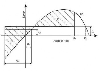
Fig 2.3.1 Severe wind and rolling
where the angles in Fig 2.3.1 are defined as follows: ![]() = angle of heel under action of steady wind
= angle of heel under action of steady wind
![]() = angle of roll to windward due to wave action(see 2.3.4)
= angle of roll to windward due to wave action(see 2.3.4)
![]()
![]()
![]() = angle of down-flooding( ) or 50
= angle of down-flooding( ) or 50![]() or , whichever is
or , whichever is
where:
![]() = angle of heel at which openings in the hull, superstructures or deckhouses which cannot be closed weathertight immerse. In applying this criterion, small openings through which progressive flooding cannot take place need not be considered as
= angle of heel at which openings in the hull, superstructures or deckhouses which cannot be closed weathertight immerse. In applying this criterion, small openings through which progressive flooding cannot take place need not be considered as
![]() = angle of second intercept between wind heeling lever
= angle of second intercept between wind heeling lever ![]() and
and ![]() curves.
curves.
2.3.2 The wind heeling levers ![]() and
and ![]() referred to in 2.3.1.1 and 2.3.1.3 are constant values at all angles of inclination and shall be calculated as follows:
referred to in 2.3.1.1 and 2.3.1.3 are constant values at all angles of inclination and shall be calculated as follows:
![]()
![]() and
and
![]()
∆
where:
![]()
![]()
![]()
= wind pressure of 504 . The value of used for ships in restricted service area may be reduced subject to the approval of the Administration
![]()
![]()
= projected lateral area of the portion of the ship and deck cargo above the waterline (m )
![]()
= vertical distance from the centre of ![]() to the centre of the underwater lateral area
to the centre of the underwater lateral area
or
![]()
approximately to a point at one half the mean draught ( )
![]()
∆= displacement ( )
![]()
Guidance Relating to the Rules for the Classification of Steel Ships 2015 81
Pt 1 Classification and Surveys
Annex 1-2 Guidance for Intact Stability Pt 1, Annex 1-2
![]()
![]()
2.3.3 Alternative means for determining the wind heeling lever( ) may be accepted, to the sat- isfaction of the Administration, as an equivalent to calculation in 2.3.2. When such alternative tests are carried out, reference shall be made based on the Guidelines developed by the International Maritime Organization*. The wind velocity used in the tests shall be 26 ![]() in full scale with uniform velocity profile. The value of wind velocity used for ships in restricted services may be reduced to the satisfaction of the Administration.
in full scale with uniform velocity profile. The value of wind velocity used for ships in restricted services may be reduced to the satisfaction of the Administration.
* Refer to the Interim Guidelines for alternative assessment of the weather criterion(IMO MSC.1/Circ.1200).
![]()
2.3.4 The angle of roll( )* referred to in 2.3.1.2 shall be calculated as follows:
* The angle of roll for ships with anti-rolling devices should be determined without taking into
account the operation of these devices unless the Administration is satisfied with the proof
that the devices are effective even with sudden shutdown of their supplied power.
![]()
where:
![]() = factor as shown in Table 2.3.4-1
= factor as shown in Table 2.3.4-1
![]() = factor as shown in Table 2.3.4-2
= factor as shown in Table 2.3.4-2
![]()
= factor as follows:
![]()
= 1.0 for round-bilged ship having no bilge or bar keels
![]() = as shown in Table 2.3.4-3 for a ship having bilge keels, a bar keel or both
= as shown in Table 2.3.4-3 for a ship having bilge keels, a bar keel or both
![]()
with:
![]()
![]() = mean moulded draught of the ship (m )
= mean moulded draught of the ship (m )
![]()
= factor as shown in Table 2.3.4-4, where ![]() is the ship roll natural period. In absence
is the ship roll natural period. In absence
![]()
![]()
Rolling period ![]() where:
where:
The symbols in Table 2.3.4-1, 2.3.4-2, 2.3.4-3 and 2.3.4-4 and the formula for the roll- ing period are defined as follows:
![]()
![]() = length of the ship at waterline ( )
= length of the ship at waterline ( )
![]()
![]()
= moulded breadth of the ship ( )
![]()
![]()
= mean moulded draught of the ship ( )
![]()
= block coefficient
![]()
![]() = total overall area of bilge keels, or area of the lateral projection of the bar keel, or sum of these areas ( )
= total overall area of bilge keels, or area of the lateral projection of the bar keel, or sum of these areas ( )
![]()
![]()
= metacentric height corrected for free surface effect ( ).
82 Guidance Relating to the Rules for the Classification of Steel Ships 2015
Pt 1 Classification and Surveys
Annex 1-2 Guidance for Intact Stability Pt 1, Annex 1-2
![]()
Table 2.3.4-1 Values of factor ![]()
| ≤2.4 | 2.5 | 2.6 | 2.7 | 2.8 | 2.9 | 3.0 | 3.1 | 3.2 | 3.4 | ≥3.5 |
| 1.0 | 0.98 | 0.96 | 0.95 | 0.93 | 0.91 | 0.90 | 0.88 | 0.86 | 0.82 | 0.80 |
Table 2.3.4-2 Values of factor ![]()
| ≤0.45 | 0.50 | 0.55 | 0.60 | 0.65 | ≥0.70 |
| 0.75 | 0.82 | 0.89 | 0.95 | 0.97 | 1.00 |
![]()
Table 2.3.4-3 Values of factor ![]()
× | 0 | 1.0 | 1.5 | 2.0 | 2.5 | 3.0 | 3.5 | ≥4.0 |
| 1.0 | 0.98 | 0.95 | 0.88 | 0.79 | 0.74 | 0.72 | 0.70 |
Table 2.3.4-4 Values of factor ![]()
| ≤6 | 7 | 8 | 12 | 14 | 16 | 18 | ≥20 |
| 0.100 | 0.098 | 0.093 | 0.065 | 0.053 | 0.044 | 0.038 | 0.035 |
(Intermediate values in these tables shall be obtained by linear interpolation)
2.3.5 The tables and formulae described in 2.3.4 are based on data from ships having:
![]()
.1
.2
.3 and
smaller than 3.5;
between - 0.3 and 0.5;
![]()
![]()
For ships with parameters outside of the above limits the angle of roll( ) may be determined with model experiments of a subject ship with the procedure described in IMO
as the alternative. In addition, the
any ship, if deemed appropriate.
Administration may accept such alternative determinations for
Guidance Relating to the Rules for the Classification of Steel Ships 2015 83
![]()
Pt 1 Classification and Surveys
Annex 1-2 Guidance for Intact Stability Pt 1, Annex 1-2
![]()
CHAPTER 3 SPECIAL CRITERIA FOR CERTAIN TYPES OF SHIPS
3.1 Passenger ships
Passenger ships shall comply with the requirements of 2.2 and 2.3.
![]()
3.1.1 In addition, the angle of heel on account of crowding of passengers to one side as defined below shall not exceed 10 .
3.1.1.1 A minimum weight of 75 ![]() shall be assumed for each passenger except that this value may be increased subject to the approval of the Administration. In addition, the
shall be assumed for each passenger except that this value may be increased subject to the approval of the Administration. In addition, the
mass and
distribution of the luggage shall be approved by the Administration.
3.1.1.2 The height of the centre of gravity for passengers shall be assumed equal to:
.1 1 ![]() above deck level for passengers standing upright. Account may be taken, if neces- sary, of camber and sheer of deck; and
above deck level for passengers standing upright. Account may be taken, if neces- sary, of camber and sheer of deck; and
.2 0.3 ![]() above the seat in respect of seated passengers.
above the seat in respect of seated passengers.
3.1.1.3 Passengers and luggage shall be considered to be in the spaces normally at their dis- posal, when assessing compliance with the criteria given in 2.2.1 to 2.2.4.
3.1.1.4 Passengers without luggage shall be considered as distributed to produce the most un- favourable combination of passenger heeling moment and/or initial metacentric height, which may be obtained in practice, when assessing compliance with the criteria given in 3.1.1 and
3.1.2, respectively. In this connection, a value higher than four persons per square metre is not necessary.
3.1.2 In addition, the angle of heel on account of turning shall not exceed 10![]() when calculated
when calculated
![]()
![]()
![]()
where:
![]()
![]()
= heeling moment ( )
![]()
![]() = service speed ( )
= service speed ( )
![]()
![]()
= length of ship at waterline ( )
![]()
∆= displacement ( )
![]()
![]()
= mean draught ( )
![]()
![]()
= height of centre of gravity above baseline ( ).
3.2 Oil tankers of 5,000 ![]() and above
and above
Oil tankers, as defined in 2(Definitions) of the INTRODUCTION, shall comply with regulation 27 of Annex I to MARPOL 73/78.
3.3 Cargo ships carrying timber deck cargoes
Cargo ships carrying timber deck cargoes shall comply with the requirements of 2.2 and 2.3 unless the Administration is satisfied with the application of alternative provision 3.3.2.
3.3.1 Scope
The provisions given hereunder apply to all ships of 24 ![]() in length and over engaged in the
in length and over engaged in the
carriage of timber deck cargoes. Ships that are provided with, and make use of, their timber load line shall also comply with the requirements of regulations 41 to 45 of the 1966 Load Line Convention.
84 Guidance Relating to the Rules for the Classification of Steel Ships 2015
Pt 1 Classification and Surveys
Annex 1-2 Guidance for Intact Stability Pt 1, Annex 1-2
![]()
3.3.2 Alternative stability criteria For ships loaded with timber between superstructures(where
deck cargoes and provided that the cargo extends longitudinally there is no limiting superstructure at the after end, the timber
deck cargo shall extend at least to the after end of the aftermost hatchway)* transversely for
the full beam of ship, after due allowance for a rounded gunwale, not exceeding 4% of the breadth of the ship and/or securing the supporting uprights and which remains securely fixed at
large angles of heel may be:
* Refer to regulation 44(2) of the International Convention on Load Lines, 1966 or the Protocol of 1988 relating thereto, as amended, as applicable.
![]()
![]()
3.3.2.1 The area under the righting lever curve( curve) shall not be less than 0.08 ![]() up to
up to ![]() = 40
= 40![]() or the angle of flooding if this angle is less than 40 .
or the angle of flooding if this angle is less than 40 .
![]()
3.3.2.2 The maximum value of the righting lever( ) shall be at least 0.25
.
![]()
taking into account the absorption of water by the deck cargo and/or ice exposed surfaces.
3.3.2.4 When determining the ability of the ship to withstand the combined wind and rolling according to 2.3, the 16![]() limiting angle of heel under
limiting angle of heel under
accretion on the
effects of beam action of steady
wind shall be complied with, but the additional criterion of 80% of the angle of deck edge
immersion may be ignored.
3.4 Cargo ships carrying grain in bulk
The intact stability of ships engaged in the carriage of grain shall comply with the requirements of the International Code for the Safe Carriage of Grain in Bulk adopted by IMO Res.MSC.23(59).*
* Refer to part C of chapter VI of the 1974 SOLAS Convention as amended.
3.5 High-speed craft
High-speed craft, as defined in 2(Definitions) of the INTRODUCTION, constructed on or after 1 January 1996 but before 1 July 2002, to which chapter X of the 1974 SOLAS Convention applies, shall comply with stability requirements of the 1994 HSC Code(IMO Res.MSC.36(63)). Any high- speed craft to which chapter X of the 1974 SOLAS Convention applies, irrespective of its date of construction, which has undergone repairs, alterations or modifications of a major character;
and a high-speed craft constructed on or after 1 July 2002, shall comply with stability requirements of the 2000 HSC Code(IMO Res.MSC.97(73)).
Guidance Relating to the Rules for the Classification of Steel Ships 2015 85
Pt 1 Classification and Surveys
Annex 1-2 Guidance for Intact Stability Pt 1, Annex 1-2
![]()